
我們在家居生活中,亮度是保護我們眼睛最重要的靈藥,家中許多高齡長者、幼童等在房間裡面,如果亮度不足,不但沒有安全感,對視力的保健,更是一大殺手。如果我們如果在家裡看到這樣的情形,當然可以馬上調整光線,但是如果我們在外面上班,就不太容易查覺到這樣隱藏的問題。
(本文由\曹永忠、許智誠、蔡英德 共同撰寫)
因此,如果我們用Arduino來照顧我們的眼睛,可以透過手機上網,直接使用瀏覽器可以監控我們家的亮度或許是個可行的應用,所以我們想到使用Arduiono,透過簡單的上網擴充卡,瞬間就讓我們的家庭進化成先進的智慧家庭。所以本文就要告訴讀者,如何簡單、快速、有效的建立一個居家亮度監控的物聯網。
Arduino Ethernet Shield 簡介
Ethernet Shield(W5100) 主要特色是把 TCP/IP Protocols (TCP, UDP, ICMP, IPv4 ARP, IGMP, PPPoE, Ethernet) 做在硬體電路上,減輕了單晶片(MCU )的負擔 (也就是 Arduino 開發板的負擔)。
Arduino 程式只要使用 Ethernet Library 便可以輕易完成連至網際網路的動作,不過 W5100 也不是沒有缺點,因為它有一個限制,就是最多只允許同時 4 個 socket 連線。
(Ethernet Library 可到Arduino.cc的官網:http://www.arduino.cc/en/reference/ethernet,下載函式庫與相關範例。)
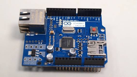
Arduino Ethernet Shield 使用加長型的 Pin header (如下圖.(a)、下圖.(b)),可以直接插到 Arduino 控制板上 (如下圖.(c)、 下圖.(d) 、下圖.(e)),而且原封不動地保留了 Arduino 控制板的 Pin Layout,讓使用者可以在它上面疊其它的擴充板(如下圖.(c) 、 下圖.(d) 、 下圖.(e))。
▼ Ethernet Shield(W5100)

比較新的 Ethernet Shield 增加了 micro-SD card 插槽,可以用來儲存檔案,你可以用 Arduino 內建的 SD library 來存取板子上的 SD card。此外,Ethernet Shield 相容於 UNO 和 Mega 2560 控制板。
Arduino 開發板跟 W5100 以及 SD card 之間的通訊都是透過 SPI bus (通過 ICSP header)。
以 UNO開發板 而言,SPI bus 腳位位於 pins 11, 12 和 13,而 Mega 2560開發板 則是 pins 50, 51 和 52。UNO 和 Mega 2560 都一樣,pin 10 是用來選擇 W5100,而 pin 4 則是用來選擇 SD card。這邊提到的這幾支腳位都不能拿來當 GPIO 使用,請讀者勿必避開這兩個GPIO腳位。
另外,在 Arduino Mega 2560 開發板上,pin 53 是 hardware SS pin,這支腳位也必須保持為 OUTPUT,不然 SPI bus 就不能動作。
在使用的時候要注意一件事,因為 W5100 和 SD card 共享 SPI bus,所以在同一個時間只能使用其中一個設備。如果你程式裏會用到 W5100 和 SD card 兩種設備,那在使用對應的 library 時就要特別留意,要避免搶 SPI bus 資源的情形。
假如你確定不會用到其中一個設備的話,你可以在程式裏明白地指示 Arduino開發板,方法是: 如果不會用到 SD card,那就把 pin 4 設置成 OUTPUT並把狀態改為 high,如果不會用到 W5100,那麼便把 pin 10 設置成 OUTPUT並把狀態改為 high。
如下圖所示,Ethernet Shield狀態指示燈 (LEDs)功能列舉如下:
- PWR: 表示 Arduino 控制板和 Ethernet Shield 已經上電
- LINK: 網路指示燈,當燈號閃爍時代表正在傳送或接收資料
- FULLD: 代表網路連線是全雙工
- 100M: 表示網路是 100 MB/s (相對於 10 Mb/s)
- RX: 接收資料時閃爍
- TX: 傳送資料時閃爍
- COLL: 閃爍時代表網路上發生封包碰撞的情形 (network collisions are detected)
資料來源:http://www.arduino.cc/en/Main/ArduinoEthernetShield
▲ W5100指示燈
實做亮度監控網站
首先,組立W5100 以太網路模組是非常容易的一件事,如下圖所示,只要將W5100 以太網路模組堆疊到任何Arduino開發板之上就可以了。
▲3 將Arduino開發板與W5100 以太網路模組堆疊組立
之後,再將組立好的W5100 以太網路模組,如下圖所示,只要將USB線差到Arduino開發板,再將RJ 45的網路線一端插到W5100 以太網路模組,另一端插到可以上網的集線器(Switch HUB)的任何一個區域網路接口(Lan Port)就可以了。
▲ 接上電源與網路線的W5100 以太網路模組堆疊卡
將Arduino 開發板的驅動程式安裝好之後,我們打開Arduino 開發板的開發工具:Sketch IDE整合開發軟體,攥寫一段程式,如下表所示之實做亮度監控網站測試程式,我們就可以讓W5100 以太網路模組堆疊卡變成一台簡易的實做亮度監控伺服器運作了。
表 1實做亮度監控網站測試程式
|
實做亮度監控網站測試程式(LightMonitorServer) |
|
/* Web Server
A simple web server that shows the value of the analog input pins. using an Arduino Wiznet Ethernet shield.
Circuit: * Ethernet shield attached to pins 10, 11, 12, 13 * Analog inputs attached to pins A0 through A5 (optional)
created 18 Dec 2009 by David A. Mellis modified 9 Apr 2012 by Tom Igoe
*/
#include <SPI.h> #include <Ethernet.h> #include <Wire.h> #include <BH1750.h>
// Enter a MAC address and IP address for your controller below. // The IP address will be dependent on your local network: byte mac[] = { 0xAA, 0xBB, 0xCC, 0xDD, 0xEE, 0xFF }; IPAddress ip(192, 168, 30, 200); IPAddress dnServer(168, 95, 1, 1); // the router's gateway address: IPAddress gateway(192, 168, 30, 254); // the subnet: IPAddress subnet(255, 255, 255, 0);
// Initialize the Ethernet server library // with the IP address and port you want to use // (port 80 is default for HTTP): EthernetServer server(80); BH1750 lightMeter;
void setup() { lightMeter.begin(); // Open serial communications and wait for port to open: Serial.begin(9600); while (!Serial) { ; // wait for serial port to connect. Needed for Leonardo only }
// start the Ethernet connection and the server: Ethernet.begin(mac, ip, dnServer, gateway, subnet); server.begin(); Serial.print("server is at "); Serial.println(Ethernet.localIP()); }
void loop() {
uint16_t lux = lightMeter.readLightLevel();
// listen for incoming clients EthernetClient client = server.available(); if (client) { Serial.println("new client"); // an http request ends with a blank line boolean currentLineIsBlank = true; while (client.connected()) { if (client.available()) { char c = client.read(); Serial.write(c); // if you've gotten to the end of the line (received a newline // character) and the line is blank, the http request has ended, // so you can send a reply if (c == '\n' && currentLineIsBlank) { // send a standard http response header client.println("HTTP/1.1 200 OK"); client.println("Content-Type: text/html"); client.println("Connection: close"); // the connection will be closed after completion of the response client.println("Refresh: 5"); // refresh the page automatically every 5 sec client.println(); client.println("<!DOCTYPE HTML>"); client.println("<html>"); // output the value of each analog input pin /*
for (int analogChannel = 0; analogChannel < 6; analogChannel++) { int sensorReading = analogRead(analogChannel); client.print("analog input "); client.print(analogChannel); client.print(" is "); client.print(sensorReading); client.println("<br />"); } */ client.print("Light: "); client.print(lux); client.println(" lx"); client.println("</html>"); break; } if (c == '\n') { // you're starting a new line currentLineIsBlank = true; } else if (c != '\r') { // you've gotten a character on the current line currentLineIsBlank = false; } } } // give the web browser time to receive the data delay(1); // close the connection: client.stop(); Serial.println("client disconnected"); } } |
範例原始碼網址:https://github.com/brucetsao/arduino_RFProgramming
如下圖所示,讀者可以看到本次實驗- 實做亮度監控網站測試程式結果畫面。
▲實做亮度監控網站測試程式結果畫面
最後,讀者可以將家中的虛擬IP透過分享器(NAT),將192.168.30.200轉成真時IP, 那麼所有在網際網路上的使用者,都可以輕易使用任何裝置,手機、平板、筆電....等等上網,使用瀏覽器查看到我們家裡的亮度了。
作者介紹
|
曹永忠 (Yung-Chung Tsao):目前為自由作家、台灣資訊傳播學會秘書長,專研於軟體工程、軟體開發與設計、物件導向程式設計,商品攝影及人像攝影。長期投入資訊系統設計與開發、企業應用系統開發、軟體工程、新產品開發管理、商品及人像攝影等領域,並持續發表作品及相關專業著作。 Email:prgbruce@gmail.com ,Line ID:dr.brucetsao Arduino部落格:http://taiwanarduino.blogspot.tw/ 範例原始碼網址:https://github.com/brucetsao/arduino_RFProgramming 臉書社群(Arduino.Taiwan):https://www.facebook.com/groups/Arduino.Taiwan/ Arduino活動官網:http://arduino.kktix.cc/ Youtube:https://www.youtube.com/channel/UCcYG2yY_u0m1aotcA4hrRgQ |

請注意!留言要自負法律責任,相關案例層出不窮,請慎重發文!